2.1.1 Naming rule
JAC200 1.5KW-4
| Identification | Voltage level |
| 4 | three-phase 380V |
| S2 | Single-phase 220V |
| Identification | Adaptive motor type |
| G | General type |
| Identification | 0.4 | 0.75 | ... | 400 |
| Adaptive motor(KW) | 0.4 | 0.75 | ... | 400 |
2.2 Introduction of various parts of the converter
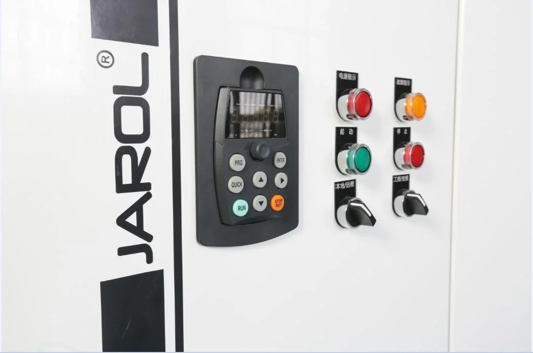
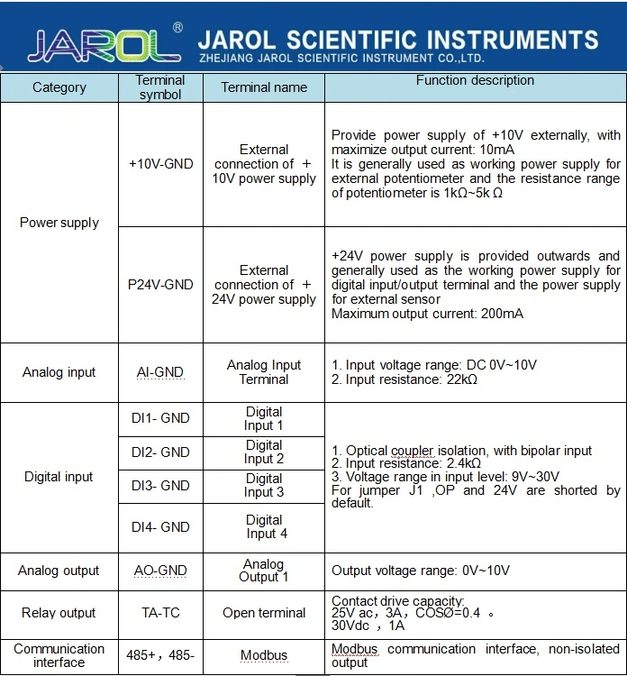
The structure types of JAC200 series converter are the plastic and metal. The external diagram is shown below.
| Item | Specification | |
| Standard functions | Control mode of Motor 1 | 0: No-speed sensor vector control (SVC); 2: V/F control |
| Maximum frequency | 50.00Hz ~ 500.00Hz | |
| Carrier frequency | 0.5kHz ~ 16.0kHz The carrier frequency is automatically adjusted based on the load features. | |
| Input frequency resolution | Digital setting: 0.01Hz; Analog setting: maximum frequency × 0.025% | |
| Starting torque | 0.5Hz/150% | |
| Basic functions | Speed range | 1:100 |
| Constant-speed accuracy | ±1% | |
| Overload capacity | 60s for 150% of the rated current | |
| Torque boost | Automatic torque boost; 0.1%~30.0% | |
| V/F curve | 0: Straight-line V/F curve 1: Multi-point V/F curve 2: Square V/F 3: 1.2th power V/F 4: 1.4th power V/F 6: 1.6th power V/F 8: 1.8th power V/F 3-8:VF relation curve between straight line VF and square VF 9: Reserved 10: VF complete separation mode 11: VF semi-separation mode | |
Acceleration / deceleration curve | Straight-line or S-curve acceleration and deceleration Four groups of acceleration/deceleration time with the | |
Voltage acceleration time of VF separation | 0.0s ~1000.0s | |
Note: The above means the time of variation from 0 V to the rated voltage of motor | ||
Voltage deceleration time of VF separation | 0.0s ~1000.0s | |
Note: The above means the time of variation from 0 V to the rated voltage of motor | ||
| DC braking | DC braking frequency: 0.00Hz~maximum frequency | |
| Braking time: 0.0s~36.0s | ||
| Braking action current value: 0.0%-100.0% | ||
| JOG control | JOG frequency range: 0.00Hz-maximum frequency | |
| JOG acceleration/deceleration time: 0.0s-6500.0s | ||
| Operation | Command source | 0: Command channel of operation panel (LED OFF) |
| 1: Command channel of the terminal (LED ON) | ||
| 2: Communication command channel (LED flashes) | ||
Selection of main frequency source X | 1: Digital setting (Preset frequency F0-08, changeable UP/DOWN, power-down memory) | |
| 2:AI1 | ||
| 3:AI2 | ||
| 4:AI3(key potentiometer) | ||
| 5: PULSE setting (DI5) | ||
| 6: Multi-stage instruction | ||
| 7: Simple PLC | ||
| 8:PID | ||
| 9: Communication reference | ||
| Input terminal | Standard: 4 digital input terminals, 1 analog input terminal, support 0 ~ 10V voltage input or 4 ~ 20mA current input | |
| Output terminal | Standard: 1 relay normally open output terminal, 1 analog output terminal, support 00 ~ 10V voltage output | |
Display and keyboard operation | LED display | Display the parameter |
Key lock and function selection | Realize partial or all key lock and define the action range of some keys to prevent misoperation | |
| Protection function | Short circuit test of electrified motor, input/output default phase protection, overcurrent protection, overvoltage protection, undervoltage protection, overheat protection, overload protection, etc. | |
Table 2-1 Technical specification of 200 series frequency converter
